

Inspired by Prof. Wildberger in his lecture series on linear algebra, I intend to implement his mathematical ideas with Flash. We shall not delve into the mathematical manipulation of matrices through linear algebra: just through vectors. This understanding, although diluting the elegance of linear algebra, is enough to launch us into some interesting possibilities of 2x2 matrix manipulation. In particular, we'll use it to apply various shearing, skewing, flipping, and scaling effects to images at runtime.
Final Result Preview
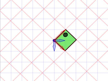
Let's take a look at the final result we will be working towards. Press the four directional keys - up, down, left, right - to see some effects we can achieve with affine transformations.
If you only use the left and right arrow keys, the fish appears to swim around in a pseudo-3D isometric space.
Step 1: Different Coordinate Spaces
Graphics are drawn onto coordinate spaces. So in order to manipulate them, especially to translate, rotate, scale, reflect and skew graphics, it is vital that we understand coordinate spaces. We generally make use of not just one, but multiple coordinate spaces in a single project - this is true not only for designers using the Flash IDE, but also for programmers writing ActionScript.
In Flash IDE this happens whenever you convert your drawings into MovieClip symbols: each symbol has its own origin.
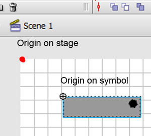
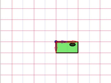
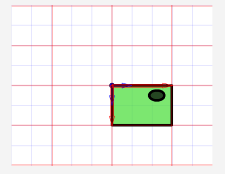
The image above shows the origin of the stage' coordinate space (red dot), and that of the symbol's coordinate space (registration point marked by crosshair). To know which space you are in currently, observe the bar beneath the timeline of Flash IDE as shown by the image below.
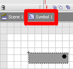
(I'm using Flash CS3, so its location may differ for CS4 and CS5.) What I want to emphasize is the existence of different coordinate spaces, and the fact that you're already familiar with using them.
Step 2: The Rationale
Now there's a good reason for this. We can use one coordinate space as a reference to change the other coordinate space. This may sound alien, so I've included the Flash presentation below to facilitate my explanation. Click and drag the red arrows. Play around with it.
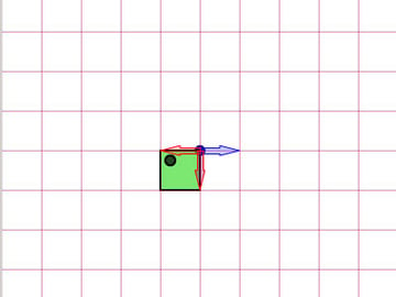
In the background is a blue grid, and in the foreground is a red grid. The blue and red arrows are initially aligned along the x- and y-axis of Flash coordinate space, whose center I have shifted to the middle of the stage. The blue grid is a reference grid; the gridlines will not change as you interact with the red arrows. The red grid, on the other hand, can be reoriented and scaled by dragging the red arrows.
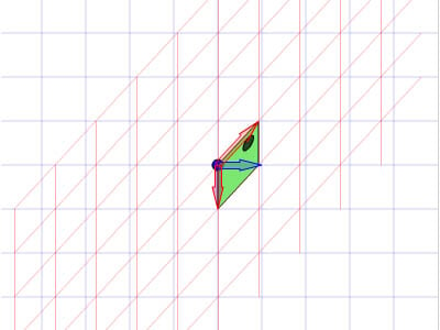
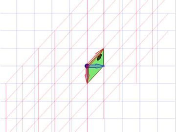
Note that the arrows also indicate an important property of these grids. They indicate the notion of a unit of x and a unit of y on their respective grid. There are two red arrows on the red grid. Each of them indicate the length of one unit on the x-axis and the y-axis. They also dictate the orientation of the coordinate space. Let's take the red arrow pointing along the x-axis and extend it to be twice as long as the original arrow (shown in blue). Observe the following images.
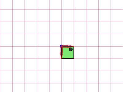
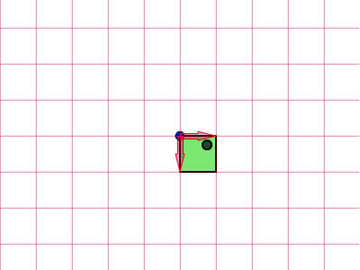

We see that the image (the green box) drawn on the red grid is now stretched horizontally, due to the fact that this red grid it is drawn onto is now twice as wide. The point I'm trying to make is rather simple: you can use one coordinate space as a basis to change another coordinate space.
Step 3: Affine Coordinate Space
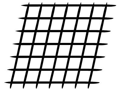
So what's an "affine coordinate space"? Well, I'm sure you are careful enough to observe that these coordinate spaces are drawn using parallel grids. Let's take the red affine space for example: there's no guarantee that both the x-axis and the y-axis are always perpendicular to each other, but rest assured that however you try to tweak the arrows, you will never arrive at such a case as below.

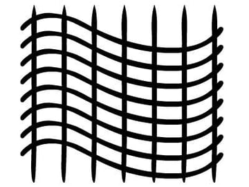
This coordinate space is not an affine coordinate space.
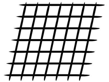
In fact, x- and y-axes usually refer to the Cartesian coordinate space, as shown below.
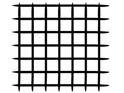
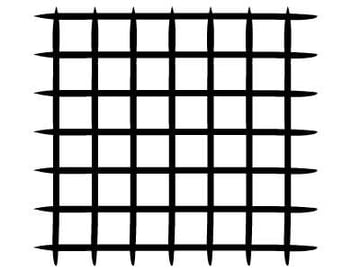
Note that the horizontal and vertical grids are perpendicular to each other. Cartesian is a type of affine coordinate space, but we can transform it to other affine spaces as we prefer. The horizontal and vertical grids do not necessarily have to be perpendicular to each other.
Example of an affine coordinate space

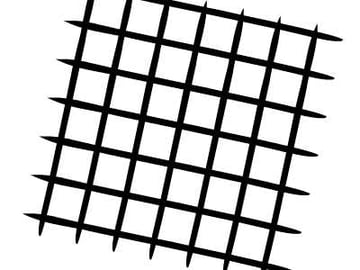
Another example of an affine coordinate space
Step 4: Affine Transformations
As you might have guessed, the affine transformations are translation, scaling, reflection, skewing and rotation.
Original affine space

Scaled affine space

Reflected affine space
Skewed affine space
Rotated and scaled affine space
Needless to say, physical properties such as x, y, scaleX, scaleY and rotation depend on the space. When we make calls to those properties, we are actually transforming affine coordinates.
Step 5: Understanding Matrix
I hope the images shown above are explicit enough to drive home the idea. This is because for a programmer working with FlashDevelop, we will not see those grids that the Flash IDE conveniently displays for designers. All of these have to live in your head.
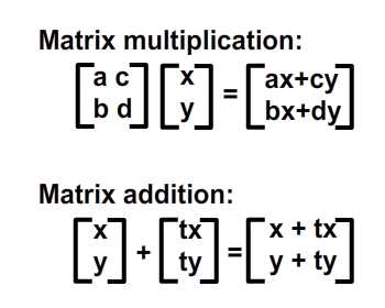
Apart from imagining these grids, we also need to enlist the help of Matrix class. Thus, having a mathematical understanding of matrices is important, so we shall revise the operations of matrix here: addition and multiplication.
Step 6: Geometrical Meaning of Matrix Addition
Matrix operations convery meanings geometrically. In other words, you can picture what they mean on a graph. Let's assume that we have four points in our coordinate space and would like to shift them to a set of new locations. This can be done using matrix addition. Check out the image below.
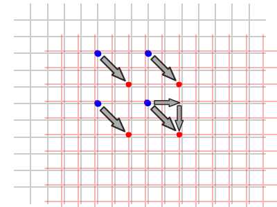
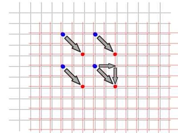
As you can see, we are actually shifting the whole local coordinate space (red grids) where these four points are drawn. The notation for performing these operations is as shown below:
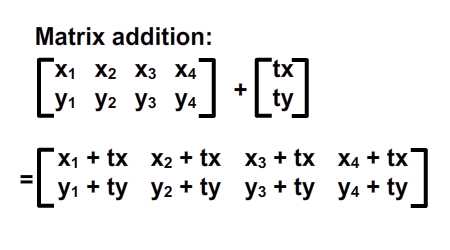
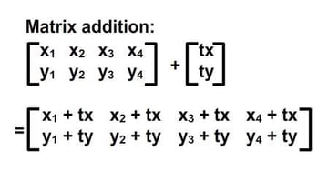
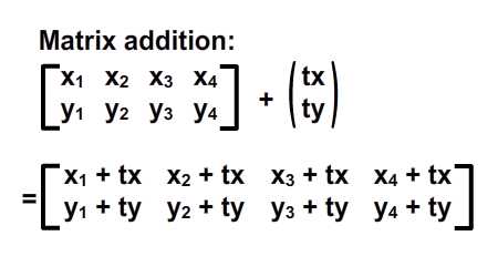
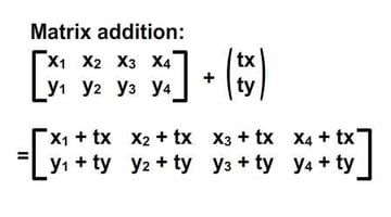
We can also see that this shift can actually be represented using a vector of (tx, ty). Let us differentiate vectors and static points in coordinate spaces by our use of parentheses and square brackets. I've rewritten them in the image below.
Step 7: ActionScript Implementation
Here's a simple implementation of matrix addition. Check out the comments:
1 |
|
2 |
public class Addition extends Sprite |
3 |
{
|
4 |
public function Addition() |
5 |
{
|
6 |
var m:Matrix = new Matrix(); //instantiate matrix |
7 |
m.tx = stage.stageWidth * 0.5; //shift in x |
8 |
m.ty = stage.stageHeight * 0.5; //shift in y |
9 |
var d:DottedBox = new DottedBox(); //create the custom graphic (dotted box is a Sprite) |
10 |
addChild(d); |
11 |
d.transform.matrix = m; //apply the matrix to our graphic |
12 |
}
|
13 |
}
|
Step 8: Geometrical Meaning of Matrix Multiplication
Matrix multiplication is somewhat more sophisticated than matrix addition but Prof Wildberger has elegantly broken it down to this simple interpretation. I shall humbly attempt to reiterate his explanation. For those who'd like to dive deeper into the understanding of linear algebra that leads to this, check out the professor's lecture series.
Let's start off by tackling the case of the identity matrix, I.
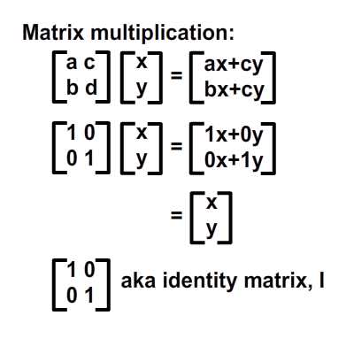
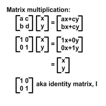
From the image above we know that multiplying an arbitrary matrix, A, by the identity matrix, I, will always produce A. Here's an analogy: 6 x 1 = 6; the identity matrix is likened to the number 1 in that multiplication.
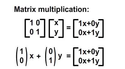
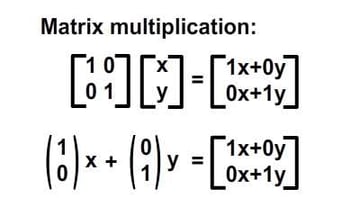
Alternatively, we can write the result in the following vector format which will greatly simplify our interpretation:
The geometric interpretation of this formula is shown in the image below.
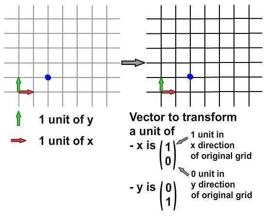
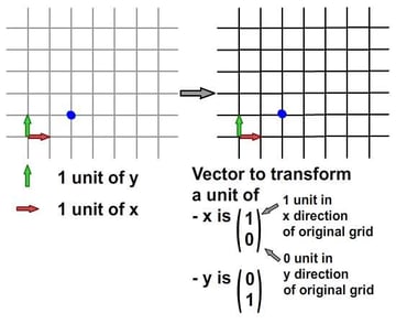
From the Cartesian grid (left grid), we can see the blue point is located at (2, 1). Now if we were to transform this original grid of x and y to a new grid (right grid) according to a set of vectors (below the right grid), the blue point will be relocated to (2, 1) on the new grid - but when we map this back to the original grid, it's the same point as before.
Because we are transforming the original grid to another grid that shares the same vectors for x and y, we see no difference. In fact, the changes of x and y in this transformation is nil. This is what it meant by identity matrix, from a geometrical point of view.
However, if we try to perform a mapping using other transformations, we shall see some difference. I know this was not the most revealing example to start with, so let's move on to another example.
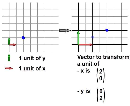
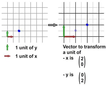
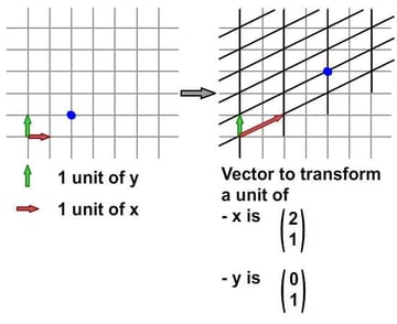
Step 9: Scaling Along X
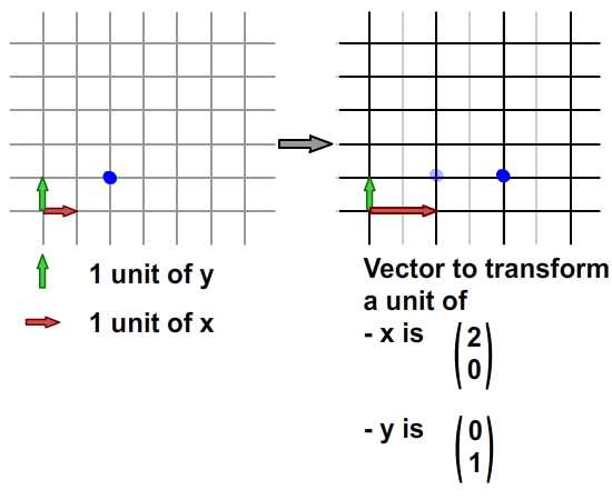
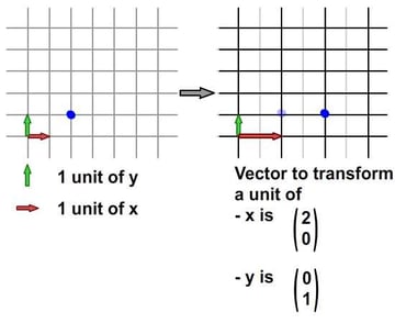
Image above demonstrates a scaling of the coordinate space. Check out the vector of x in transformed coordinate space: one unit of the transformed x accounts for two units of the original x. On the transformed coordinate space, the coordinate of the blue point is still (2, 1). However, if you try to map this coordinate from the transformed grid onto the original grid, it is (4, 1).
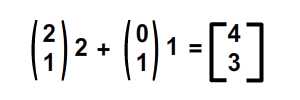
This whole idea is captured by the image above. How about the formula? The result should be consistent; let's check it out.
I'm sure you recall these formulae. Now, I've added their respective meanings.
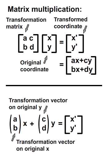
Now to check out the numerical result of our scaling example.
- Original coordinate: (2, 1)
- Vector on transformed x-axis: (2, 0)
- Vector on transformed y-axis: (0, 1)
- Expected result: (2*2 + 0*1, 0*2 + 1*1) = (4, 1)
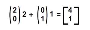
They do agree with each other! Now we can happily apply this idea to other transformations. But before that, an ActionScript implementation.
Step 10: ActionScript Implementation
Check out the ActionScript implementation (and the resulting SWF) below. Note that one of the overlapping boxes is being stretched along x by a scale of 2. I have highlighted the important values. These values will be tweaked in the later steps to represent different transformations.
1 |
|
2 |
public class Multiplication extends Sprite |
3 |
{
|
4 |
public function Multiplication() |
5 |
{
|
6 |
var ref:DottedBox = new DottedBox(); //create reference graphic |
7 |
addChild(ref); ref.x = stage.stageWidth * 0.5; ref.y = stage.stageHeight * 0.5; |
8 |
|
9 |
var m:Matrix = new Matrix(); //instantiate matrix |
10 |
m.tx = stage.stageWidth * 0.5; //shift in x |
11 |
m.ty = stage.stageHeight * 0.5; //shift in y |
12 |
m.a = 2; m.c = 0; |
13 |
m.b = 0; m.d = 1; |
14 |
var d:DottedBox = new DottedBox(); //create the custom graphic |
15 |
addChild(d); |
16 |
d.transform.matrix = m //apply the matrix onto our graphic |
17 |
}
|
18 |
}
|
Step 11: Scaling X and Y
Here we've scaled the grid by a factor of two along both the x- and y-axes. The blue point is at (2, 1) in the original grid before the transformation, and (4, 2) in the original grid after the transformation. (Of course, it's still at (2, 1) in the new grid after the transformation.)
And to confirm the result numerically...
... they match again! To see this in the ActionScript implementation, just change the value of m.d from 1 to 2.
(Note that the direction of stretch from y is downwards, not upwards, because y increments downwards in Flash but upwards in the normal Cartesian coordinate space that I used in the diagram.)
Step 12: Reflection
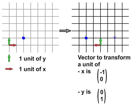
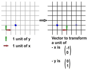
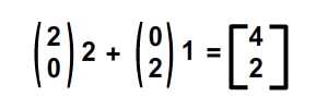
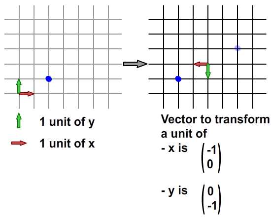
Here we've reflected the grid along the x-axis using these two vectors, so the position of the blue point in the original grid changes from (2, 1) to (-2, 1). The numeric calculation is as follows:
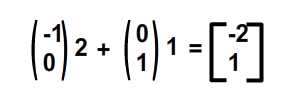
The ActionScript implementation is the same as before, but using these values instead: m.a = -1, m.b = 0 to represent the vector for the x transformation, and: m.c = 0 and m. d = 1 to represent the vector for the y transformation.
Next, what about reflecting simultaneously on x and y? Check out the image below.
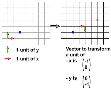
Also, numerically computed in image below.
For the ActionScript implementation... well, I'm sure you know the values to put into the matrix. m.a = -1, m.b = 0 to represent the vector for the x transformation; m.c = 0 and m. d = -1 to represent the vector for the y transformation. I've included the final SWF below.
Step 13: Skewing and Shearing
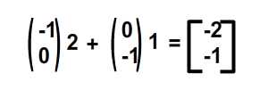
Skewing comes with a little fun. For the case of the image below, the transformed grid has had its x-axis reoriented and scaled. Compare the red arrows in both grids below: they are different, but the y-axis remains unchanged.
Skewing
Visually, it seems that distortion happens along the y-direction. This is true because our transformed x-axis now has a y-component in its vector.
Numerically, this is what happens...
In terms of implementation, I've listed the tweaks below.
m.a = 2m.b = 1m.c = 0m.d = 1
I'm sure at this point you'd like to try out things yourself, so go ahead and tweak
- the orientation of transformed y-axis while maintaining the x-axis
- the orientation of both axes altogether
I have included the Flash output for both cases as below. For readers who'd like some help with these values, check out Multiplication_final.as in the source download.
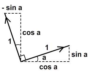
Step 14: Rotation
I consider rotation a subset of skewing. The only difference is that in rotation, the magnitude of a unit of both x and y-axis is maintained, as is the perpendicularity between the two axes.
ActionScript actually provides a method in the Matrix class, rotate(), to do this. But let's go through this anyway.
Now we do not want to alter the magnitude of a unit length in x and y from the original grid; just to change the orientation of each. We can make use of trigonometry to arrive at the result shown in the image above. Given an angle of roation, a, we'll get the desired result by using vectors of (cos a, sin a) for x-axis and (-sin a, cos a) for y-axis. The magnitude for each new axis will still be one unit, but each axis will be at an angle of a, compared to the originals.
For Actionscript implementation, assuming that the angle, a, is 45 degrees (that is, 0.25*Pi radians), just tweak the matrix values to the following:
1 |
|
2 |
var a:Number = 0.25*Math.PI |
3 |
m.a = Math.cos(a); m.c = -1*Math.sin(a); |
4 |
m.b = Math.sin(a); m.d = Math.cos(a); |
The full source can be referred to in Multiplication_final.as.
Step 15: Application
Having a vector interpretation of a 2x2 matrix opens up space for us to explore. Its application in manipulating bitmaps (BitmapData, LineBitmapStyle, LineGradientStyle, etc.) is widespread - but I think I'll save that for another tutorial. For the case of this article, we shall attempt to skew our sprite at run-time so that it looks like it's actually flipping in 3D.
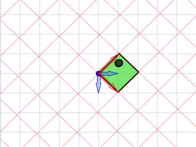
View of a pseudo-3D isometric world
From the image above we can see that, in a world with an isometric view, any graphic that's "standing" keeps its y-axis vector unchanged while the x-axis vector is rotates. Note that a unit of length for the x- and y-axis does not change - in other words, no scaling should happen in either axis, just rotation around the x-axis.
Here's an example of this idea in Flash. Click anywhere on the stage and begin dragging around to see the fish skew. Release to stop your interaction.
Here's the important bit of Actionscript. I've highlighted the crucial lines that handle the x-axis rotation. You can also refer to FakeIso.as.
1 |
|
2 |
private var f1:Fish, m:Matrix; |
3 |
private var disp:Point; |
4 |
private var axisX:Point, axisY:Point; |
5 |
|
6 |
public function FakeIso() { |
7 |
disp = new Point(stage.stageWidth * 0.5, stage.stageHeight * 0.5); |
8 |
m = new Matrix(); |
9 |
m.tx = disp.x; m.ty = disp.y; //displace to the center of stage |
10 |
f1 = new Fish(); addChild(f1); |
11 |
f1.transform.matrix = m; //apply transformation to onto fish |
12 |
|
13 |
axisX = new Point(1, 0); //vector for x - axis |
14 |
axisY = new Point(0, 1); //vector for y - axis |
15 |
stage.addEventListener(MouseEvent.MOUSE_DOWN, start); //start interaction |
16 |
stage.addEventListener(MouseEvent.MOUSE_UP, end); //end interaction |
17 |
}
|
18 |
|
19 |
private function start(e:MouseEvent):void { |
20 |
f1.addEventListener(Event.ENTER_FRAME, update); |
21 |
}
|
22 |
|
23 |
private function end(e:MouseEvent):void { |
24 |
f1.removeEventListener(Event.ENTER_FRAME, update); |
25 |
}
|
26 |
|
27 |
private function update(e:Event):void { |
28 |
axisX.setTo(mouseX - f1.x, mouseY - f1.y); //determine orientation (but magnitude changed as well) |
29 |
axisX.normalize(1); //fix magnitude of vector with new orientation to 1 unit |
30 |
apply2Matrix(); //apply matrix onto fish |
31 |
}
|
32 |
|
33 |
private function apply2Matrix ():void { |
34 |
m.setTo(axisX.x, axisX.y, axisY.x, axisY.y, disp.x, disp.y); |
35 |
f1.transform.matrix = m; |
36 |
}
|
Here, I have used the Point class for storing vectors.
Step 16: Add Keyboard Control
In this step, we shall attempt to add keyboard controls. The fish's location will update according to its velocity, velo. We'll define incremental steps for positive (clockwise) rotation and negative (anti-clockwise) rotation as well.
1 |
|
2 |
velo = new Point(1, 0); //velo will be used to define x-axis |
3 |
axisY = new Point(0, 1); |
4 |
delta_positive = new Matrix(); delta_positive.rotate(Math.PI * 0.01); //positive rotation |
5 |
delta_negative = new Matrix(); delta_negative.rotate(Math.PI * -0.01); //negative rotation |
Upon a key press, velo will rotate:
1 |
|
2 |
private function keyUp(e:KeyboardEvent):void { |
3 |
if (e.keyCode == Keyboard.LEFT) { |
4 |
velo = delta_negative.transformPoint(velo) //rotate velo counter-clockwise |
5 |
}
|
6 |
else if (e.keyCode == Keyboard.RIGHT) { |
7 |
velo = delta_positive.transformPoint(velo) //rotate velo clockwise |
8 |
}
|
9 |
}
|
Now for each frame, we shall attempt to color the front side of the fish, and skew the fish as well. If the velocity, velo, has a magnitude of more than 1 and we apply it to the fish's matrix, m, we will get a scaling effect as well - so in order to eliminate this possibility, we shall normalise the velocity and then only apply that to the fish's matrix.
1 |
|
2 |
private function update(e:Event):void { |
3 |
var front_side:Boolean = velo.x > 0 //checking for the front side of fish |
4 |
if (front_side) { f1.colorBody(0x002233,0.5) } //color the front side of fish |
5 |
else f1.colorBody(0xFFFFFF,0.5) //white applied to back side of fish |
6 |
|
7 |
disp = disp.add(velo); //update current displacement with velocity |
8 |
var velo_norm:Point = velo.clone(); //in case velo > 0, we need to recalculate 1 unit of length for x. |
9 |
velo_norm.normalize(1); //note that x-axis more than 1 will perform scaling. We dont want that for now |
10 |
m.setTo(velo_norm.x, velo_norm.y, axisY.x, axisY.y, disp.x, disp.y); |
11 |
f1.transform.matrix = m; |
12 |
}
|
Step 17: Your Fish
Click the stage, then press the left and right arrow keys to see make the fish change direction.
Step 18: Another Keyboard Control
To spice things up, let us allow the control of the y-axis vector as well.
1 |
|
2 |
private function keyUp(e:KeyboardEvent):void { |
3 |
if (e.keyCode == Keyboard.LEFT) { |
4 |
velo = delta_negative.transformPoint(velo) |
5 |
}
|
6 |
else if (e.keyCode == Keyboard.RIGHT) { |
7 |
velo = delta_positive.transformPoint(velo) |
8 |
}
|
9 |
if (e.keyCode == Keyboard.UP) { |
10 |
axisY = delta_negative.transformPoint(axisY) |
11 |
}
|
12 |
else if (e.keyCode == Keyboard.DOWN) { |
13 |
axisY = delta_positive.transformPoint(axisY) |
14 |
}
|
15 |
}
|
Also to determine the front side of the fish, we now need to incorporate the y-axis in. Here's the code for that:
1 |
|
2 |
var front_side:Boolean = velo.x * axisY.y > 0 |
3 |
if (front_side) { f1.colorBody(0x002233,0.5) } |
4 |
else f1.colorBody(0xFFFFFF,0.5) |
Step 19: Your No-So-Regular Fish
Well, for some the result of controlling both axes may prove to be a little confusing, but the point is that you now can skew your fish, translate it, reflect it, and even rotate it! Try out the combos of up + left, up + right, down + left, down + right.
Also, see if you can maintain the "front" side of fish (fish will be grayed). Hint: Tap up continuously, then left, then down, then right. You are making a rotation!
Conclusion
I hope you find matrix math a valuable asset to your projects after reading this article. I'm hoping to write a little more on applications of 2x2 matrix in little Quick Tips branching out of this article, and on Matrix3d which is essential for 3D manipulations. Thanks for the read, terima kasih.
 By
By


