
The ColorMatrixFilter and ConvolutionFilter can be used to visually transform your Flash objects. In this article, I'll show you how easy they are to manipulate, using a cool tool I built for simple experimentation.
Introduction
Have you guys ever experimented with Flash's ColorMatrix and Convolution filters? I was digging around in a quest to find some interesting stuff you can do with Flash and I bumped into them. Experimenting with them can deliver some awesome results.
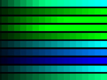
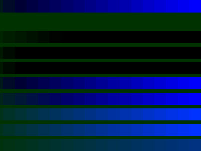
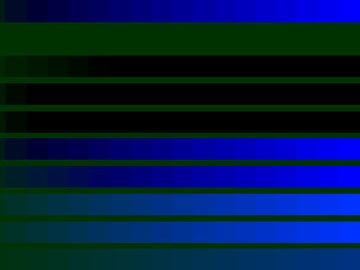
I've written an EffectsTester to make it easy to experiment with them. Check out these camshots I took while playing around with it:


Now, if you find that interesting, let me walk you through what these two filters are all about.
The Color Matrix Filter
The Color Matrix Filter is used to manipulate the color of a display object.
Let me explain the exact calculation performed by the ColorMatrixFilter. Every pixel in an image is a mixture of red, green, and blue. These primary colors, when combined, can make any other color:

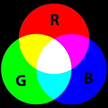
Image from Wikimedia Commons. Thanks to Mike Horvath and jacobolus.
The amount of red in a pixel can vary from zero (no red at all) to 255. Same for green and blue. So, from the image above, you can see that a pure yellow pixel has red = 255, and green = 255. White has red, green, and blue all set to 255. Black has all three set to zero.
The color matrix filter looks at each pixel in a source image and changes them based on how much red, blue, and green is in the pixel. You end up with a whole new image; the destination image.
Here's How it Works
First, let's concentrate on these three values:
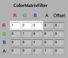
Let's label these values a[0], a[1], and a[2] in turn. Now, think about just one single pixel in the entire source image (the one in the top-left corner will do). Let's call the amount of red in that srcR, the amount of green srcG and the amount of blue srcB.
The question is: how much red will be in that pixel of the destination image, destR? Flash uses this calculation:
1 |
|
2 |
destR = ( a[0] * srcR ) + ( a[1] * srcG ) + ( a[2] * srcB ); |
Here you can see that a[0] is 1, while a[1] and a[2] are both zero, so:
1 |
|
2 |
destR = ( 1 * srcR ) + ( 0 * srcG ) + ( 0 * srcB ); |
3 |
//which means...
|
4 |
destR = srcR; |
There's no change! But what if we changed a[0] to zero and a[1] to 1? Then:
1 |
|
2 |
destR = ( 0 * srcR ) + ( 1 * srcG ) + ( 0 * srcB ); |
3 |
//which means...
|
4 |
destR = srcG; |
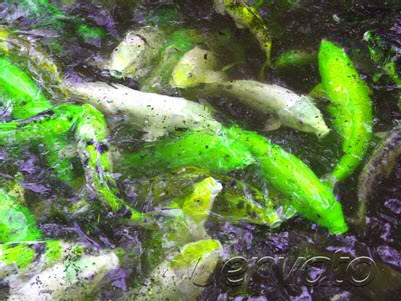
...the amount of red in the destination pixel would be equal to the amount of green in the source pixel! Furthermore, if you changed the second row to read "1 0 0", then the amount of green in the destination pixel would be equal to the amount of red in the source pixel; you would have swapped them over and your orange fish would turn into green ones:


You're probably wondering about the A column and row and about the Offset column. Well, A stands for alpha, which means transparency. The A values have much the same effect as the R G B values, but since none of these sample images are transparent, it's hard to demonstrate. The Offset column lets you simply increase or decrease the amount of red, blue, or green in the destination pixel: type -255 into the R row's Offset column and you'll see that there is no longer any red in the image.
Experiment
I realize it's tricky to understand this just from reading about it, so we're going to look at some cool example effects. That's much more fun, anyway. But first, for the curious, here's the actual mathematical formula Flash uses:
1 |
|
2 |
destR = ( a[0] * srcR ) + ( a[1] * srcG ) + ( a[2] * srcB ) + ( a[3] * srcA ) + a[4]; |
3 |
destG = ( a[5] * srcR ) + ( a[6] * srcG ) + ( a[7] * srcB ) + ( a[8] * srcA ) + a[9]; |
4 |
destB = ( a[10] * srcR ) + ( a[11] * srcG ) + ( a[12] * srcB ) + ( a[13] * srcA ) + a[14]; |
5 |
destA = ( a[15] * srcR ) + ( a[16] * srcG ) + ( a[17] * srcB ) + ( a[18] * srcA ) + a[19]; |
(Each of the values you see in the 5x4 matrix can vary between -255 and 255.)
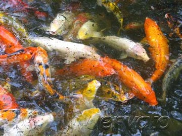
Take a look at the "Color Chart" sample image:
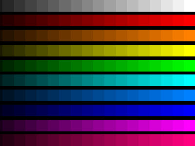

Now, let's say you want to remove all red color from the picture. Simply set all the values in the R row to zero:
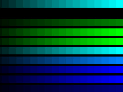
This means:
1 |
|
2 |
destR = ( 0 * srcR ) + ( 0 * srcG ) + ( 0 * srcB ) + ( 0 * srcA ) + 0; |
3 |
//which means:
|
4 |
destR = 0 + 0 + 0 + 0 + 0; |
5 |
//so:
|
6 |
destR = 0; |
Now let's say you want to add some more green where there was previously red. Put "1" at input 0x1, so the G row reads "1 1 0 0 0":
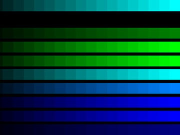
Let's now achieve something very strange by changing the G row to "0 -1 0 0 50":
What just happened? As an example, if at some random pixel you had green = 30, it was multiplied with '-1' and afterwards 50 was added, so the result would be: (30 * -1) + 50 = 20.
Therefore, a type of threshold is created: for each pixel with a green value greater than 50, its transformed pixel will be completely turned off. Why? Well, suppose the pixel's green channel has a value of 51:
1 |
|
2 |
destG = ( 0 * srcR ) + ( -1 * srcG ) + ( 0 * srcB ) + ( 0 * srcA ) + 50; |
3 |
//remember srcG = 51:
|
4 |
destG = 0 + (-51) + 0 + 0 + 50; |
5 |
//so:
|
6 |
destG = - 51 + 50; |
7 |
//so:
|
8 |
destG = -1; |
9 |
//but a pixel can't have a negative amount of green, so this is just set to zero:
|
10 |
destG = 0; |
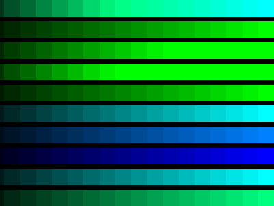
Now try this:

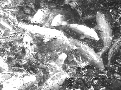
All pixels with green values greater than 50 get turned off and those with green values below 50 have all three color channels increased. This allows you to see areas of the image that have only a very small amount of green, as with the fish image:
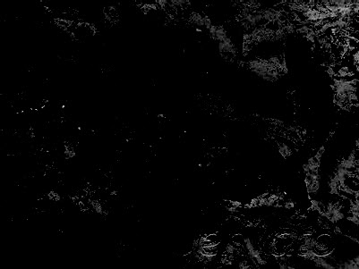
 x
xHere, only the pixels with an amount of green less than 50. The darker the pixel, the more green there is in the original image. That's the basic principle anyway. I know it may seem complicated at first, but play with it and you'll get it eventually :)
Grayscale
OK, let's go for something standard: a grayscale image. Change your matrix like so:
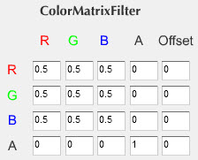
You've got a grayscale. Nice :)

Inverted Colors
Let's achieve another popular color state: Inverted Colors.
To invert the colors, we need to make it so that every pixel with a red value of 255 has a red value of zero, and vice-versa. Same for the other two colors. So we need to make Flash run code that looks like this:
1 |
|
2 |
destR = 255 - srcR; |
3 |
destG = 255 - srcG; |
4 |
destB = 255 - srcB; |
But that's easy! All we have to do is set the matrix like this:
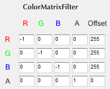
Tada! Electric fish:


More Effects
Most of the more exotic effects that can be achieved by the ColorMatrixFilter are done by setting a negative value for a color and a positive value for offset - or vice-versa. Put "-1" from 0x3 to 2x3 (the alphas) and 255 for offset of the alpha (4x3).
Wow, now I know now how they made Terminator 2 :)
Honestly, I am not really sure what I just did - calculations become really hard to track after a while.
Although it's possible to understand how the ColorMatrixFilter works from a mathematical point of view, realistically it's going to remain a matter of playing around with it. You can never be exactly sure what is going to pop up when you put some specific values. That's why I made this EffectsTester. So play around. Make yourself metallic green, or red, or colorless.
Real World Application
When you've got an effect you like, you can apply it to any DisplayObject (MovieClip, Sprite, Bitmap...) in your own code like this:
1 |
|
2 |
//first import ColorMatrixFilter up at the top of your code:
|
3 |
import flash.filters.ColorMatrixFilter; |
4 |
|
5 |
//...later on:
|
6 |
var filters:Array = new Array(); |
7 |
//for everything after " = new", copy and paste from the "Grab The Code" box of EffectsTester:
|
8 |
var cmf:ColorMatrixFilter = new ColorMatrixFilter(new Array(-1,0,0,0,255,0,-1,0,0,255,0,0,-1,0,255,0,0,0,1,0)); |
9 |
//the next two lines apply the filter to your display object:
|
10 |
filters.push( cmf ); |
11 |
myDisplayObject.filters = filters; |
Now let's look at the convolution filter.
The Convolution Filter
From Adobe's class reference:
A convolution combines pixels in the input image with neighboring pixels to produce an image. A wide variety of image effects can be achieved through convolutions, including blurring, edge detection, sharpening, embossing, and beveling.
The ConvolutionFilter loops through all pixels of a display object. For each of them, it uses the center value in the matrix as the value of the current pixel being manipulated. For example, in a 3 x 3 matrix, the center value is at (1, 1). It then multiplies the values from the matrix by the surrounding pixels and adds the resulting values for all pixels to get the value for the resulting center pixel.
Understanding the exact math beneath the Convolution matrix is worth a whole new article, so I won't cover all this here. If you want to get into it, check out this post on adobe.com.
However, a simple play around with the values will eventually give you all possible effects you can achieve. And it will be fun :) So let's see what can we do!
Experiment
The convolution filter uses a matrix, just like the color matrix filter. Again, the values vary between -255 and 255. And again, you achieve most of the interesting effects when combining negative values with positive ones.
Let me share with you my observations of how this thing works. Try increasing some random value from the matrix. Whichever you pick, it will lighten the picture; if you want the picture to stay at normal brightness, make sure the value of "divisor" is equal to the sum of all the values in the matrix.
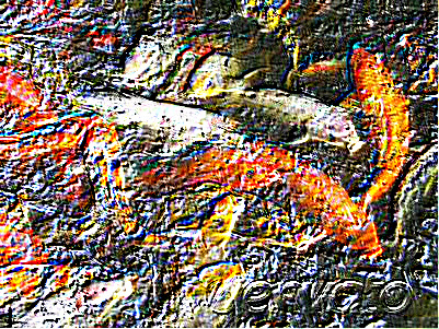
Now if you try to lower a random value below zero while keeping at least one other above zero, you get something going on there. It affects your edges:
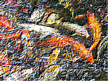
Here is a nice one: want to look like a soldier? :) Try these values:
Now lower the "divisor" value to "-1" to become a soldier on a mission at night.
A lot of stuff can be achieved if you hold your mouse button a bit more :) Lower and raise some values to extremes. Don't forget to adjust the "divisor" - it's crucial. Enlarge your matrix. Make it 5x5, for example.
Real World Application
To apply the effect in your own code, use the filters object, just as you did for the ColorMatrixFilter:
1 |
|
2 |
//first import ConvolutionFilter up at the top of your code:
|
3 |
import flash.filters.ConvolutionFilter; |
4 |
|
5 |
//...later on:
|
6 |
var filters:Array = new Array(); |
7 |
//for everything after " = new", copy and paste from the "Grab The Code" box of EffectsTester:
|
8 |
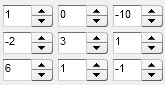
var cf:ConvolutionFilter = new ConvolutionFilter(3,3,new Array(1,0,-10,-2,3,1,6,1,-1),0); |
9 |
//the next two lines apply the filter to your display object:
|
10 |
filters.push( cf ); |
11 |
myDisplayObject.filters = filters; |
Finally: try combining both filters.
1 |
|
2 |
//first import the filter classes up at the top of your code:
|
3 |
import flash.filters.ColorMatrixFilter; |
4 |
import flash.filters.ConvolutionFilter; |
5 |
|
6 |
//...later on:
|
7 |
var filters:Array = new Array(); |
8 |
//for everything after " = new", copy and paste from the "Grab The Code" box of EffectsTester:
|
9 |
var cmf:ColorMatrixFilter = new ColorMatrixFilter(new Array(-1,0,0,0,255,0,-1,0,0,255,0,0,-1,0,255,0,0,0,1,0)); |
10 |
var cf:ConvolutionFilter = new ConvolutionFilter(3,3,new Array(1,0,-10,-2,3,1,6,1,-1),0); |
11 |
|
12 |
//the next three lines apply the filters to your display object:
|
13 |
filters.push( cf ); |
14 |
filters.push( cmf ); |
15 |
myDisplayObject.filters = filters; |
Have fun playing with these filters and post any results you get in the comments! Thanks for reading.
 By
By


